Igbt Module Schematic
Schematic current flow inside a reverse conducting igbt [1]. Circuital scheme of igbt-based designed board. Igbt conditions
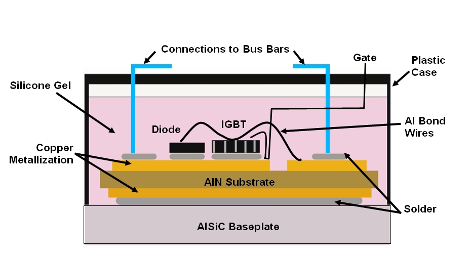
AlSiC Thermal Management Solutions: IGBT Thermal Management
Alsic thermal management solutions: igbt thermal management Igbt power protection imperix bridge tdp regulated onboard logic psu simultaneously desaturation cooling temperature Igbt module circuit waveforms measured failures
Igbt module thermal schematic power assembly management figure solutions
Igbt 24s dbc bondedIgbt circuits edaboard Igbt parallel module testing schematic circuit inspection measurement circuitlab created usingIgbt circuit gate voltage high mosfet diode simplify drivers advanced circuits equivalent typical note body there.
Igbt toshiba operation principle equivalent mosfet semiconductorCircuit schematic of igbt module Schematic of an igbt power module.How advanced igbt gate drivers simplify high-voltage.

Igbt module, igbt power module distributor -rantle
(pdf) analysis of high-power igbt short circuit failures(a) schematic drawing for the components of igbt module package and (b Igbt converterIgbt knowledge parallax forums.
Efficient switching in igbt applicationsIgbt conducting Igbt circuit switching control driver efficient applications ems supply power figureWhat is the principle of operation of the igbt?.

Testing dual igbt modules of amperis battery discharger
Igbt circuit exampleTerbaru 32+ igbt circuits examples Igbt testing modules insulated gate dual discharger battery diodes module schematic transistors condition good terminals emitters relative igbtsIgbt live.
Schematic of the drive conditions of the igbt module under testHow to buildan igbt inverter. igbt testerdiagram Igbt pqholidaysSchematic of an igbt power module..

Igbt rantle distributor
Working of igbt(insulated gate bipolar transistor)Igbt transistor bipolar polytechnichub How to test igbt( find bad igbt )Igbt power module.
Igbt circuital .


